Pumps, Plows and Prizes!

There are instructions for that…
After installing the new motor, we were ready to get the hydraulic pump attached and ready to work.  Before remounting the pump, Barry wanted to replace the shaft seal, to cure the slow leak.  As noted elsewhere, Newgren used the same pump found on an International Harvester Model C tractor.  A search found that the seal was available and an order placed.  When the seal arrived, it was a pretty simple process to take the pump apart and remove the old seal.  The new seal was tapped in place and we were ready to mount the pump.

Above is pictured a portion of the pump bracket and the crankshaft pulley with the “special nut” installed.  Set screws (small dots) are visible on either side of the threaded crankshaft 

The pump connects to the crankshaft with a “special nut” (a steel bar with a short stud at each end), a rubber disk and a matching steel bar with studs that fits on the pump shaft.  We have installed and removed the pump probably a dozen times over the years, so don’t need the installation instructions.  Or so we thought.

We quickly mounted the pump and started the engine.  The lift worked perfectly for a few minutes.  And then it stopped working.  A quick inspection showed that the special nut had come loose from the pulley and was allowed the coupling to slip.  The pump wasn’t turning fast enough to work.  No problem, we just need to tighten the “special nut” on the crankshaft.  Making sure it was tight, we tried again, with the same results.

Time for a bigger hammer, or in this case a bar between the studs to REALLY tighten the nut.  This did keep the nut from coming loose, but created a huge oil leak out the end of the crankshaft!  Rather than report the hours spent trying to stop the leak, we will simply report the fix.  We needed a new “slinger” behind the timing chain cover and, mostly importantly, we used Permatex Ultra Black sealer between the shaft and pulley.  Time to attack the problem of the nut coming loose – over tightening was not the answer.
It was clear that the problem had surfaced with the pump seal replacement.  More force was required to turn the pump when it was not leaking (a good thing).  The original instructions called for two small set screws on the “special nut” to be removed with the nut in place against the pulley.  Two small holes were to be drilled into the face of the pulley (using the set screw holes as a guide).  We had not figured out how to do this without removing the front of the jeep, so had just tightened the set screws against the pulley face.
Figuring that the average farmer or Willys dealer would have not wanted to remove the radiator and grill, there must have been a method for drilling the holes.  We have a right-angle power drill and it worked perfectly for the task.  Regardless of the method used, the properly installed special nut hasn’t come loose.  Another lesson learned for us.  Follow the instructions!
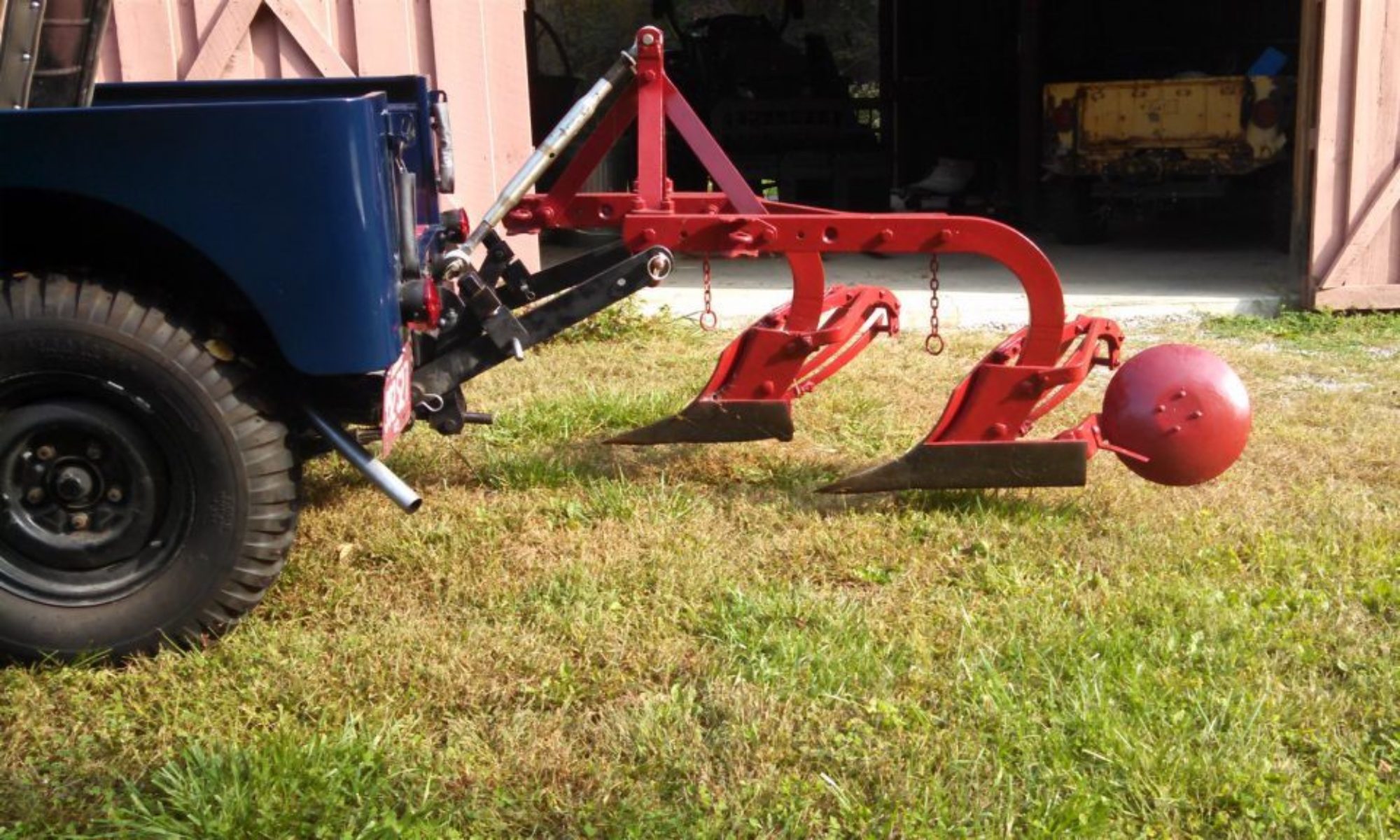
A Newgren plow of our own!


Our friend Craig loaned us his early Newgren plow to display with our jeep a couple of years ago.  Since then we have been telling Craig that if he won’t sell us his plow, he should help us find our own.  And he did just that!
Craig had sent me a note about attending an antique tractor parts meet.  Not being able to attend, Barry did tell him to bring home a Newgren plow if he saw one.  Craig sent back an ad for a Newgren plow near Knoxville, TN.   Three days later, Barry made a flying trip to pick up the plow.
It is a beautiful later model 2-12 slat plow.  It is missing the coulters and the gauge wheel bracket, but the other parts are in excellent condition.  We will be looking for the missing parts and working with plow expert Clint Dixon to bring it back to its original state.  Clint says that he knows of only 7 other examples of the later tall mast Newgren plows.  That makes it even more exciting.
A prize of our own…


In addition to attending antique machinery shows, we have wanted to take the farm jeep to the local county fair.   We finally had a chance to enter the antique farming exhibit.  While we hadn’t expected to be judged, we ended up with a blue ribbon.   The blue ribbon was for “best in class” and being the only entry in the jeep class, we were an automatic winner.  Still, we will proudly display the ribbon in garage.
This was also the first time we have displayed the jeep backwards.  It had become clear that with the front end of the jeep lined up with the fronts of other tractors we presented no clues about the jeep as a tractor.   Visitors would glance at the jeep and walk on down the line.  If we could get them to the rear of the display, interest went way up.
So the fair offered an opportunity to try our reverse display.  It was an absolute success.  This is how we will display the jeep at future shows.

Out with the old… In with the older…

Ole Blue arrived without a motor and the engine we purchased had most likely spent is former life in a welder application.  But an L-134 is an L-134 and the engine got us on the road.  However, the engine smoked, we had some oil pan issues and even after an oil pump change we saw very low pressure.  More critical was a noise from the clutch.  We had picked up a rebuilt L-134 engine with the idea of doing a swap and fixing the clutch.  Like many of our projects, this one took some time, but we did get the job done.


Unbolt this, disconnect that
Since this was an engine swap, we took advantage of the jeeps simple constructions.  By removing the fenders, grill and radiator, we had easy access to the engine.  We did have to remove all the wiring in the front end, but again, the jeep is a simple vehicle.  The most important tool at this point is an engine hoist with a load leveler the attaches to the head bolts.  The second most important tool is a digital camera to take lots of pictures, especially of the wiring, to aid in the reassembly.
With only a couple of “hum, why isn’t it releasing”, the engine came free of the bellhousing and the transmission shaft.  We had chosen to unbolt the engine from the front mounts.  Hindsight tells us that should have unbolted the mounts from the frame.  We had to “lift” the front of the block, thus binding the engine on the shaft more than necessary.
There’s your problem
A quick look at the throw-out bearing and transmission shaft showed no wear or problems.  So the next task with the engine out was to remove the clutch.  As soon as the pressure plate was removed, the source of the clutch noise was evident.  The springs on the clutch disk had made contact with the bolts on the flywheel. Our installation way-back-when was our first and we assumed that the flywheel that came with the engine was the correct one.  With the new engine setting next to the old, the difference in the flywheels was obvious.
The old flywheel had been machined in the middle, lessening the clearance for the clutch disk.   So the good news was that we weren’t facing a major problem.  We had, not knowing what we might find, ordered a complete new clutch assemble.  We could have gotten by with just a new clutch disk, but at this point replacing everything seemed the wise path.
Mother of invention
The flywheel on the new engine was very rusty.  We decided to remove the flywheel to get it cleaned off.  The flywheel is held on by bolts, so removal should be simple.  Not so fast.  The flywheel fits on a hub at the end of the crankshaft and it is a tight fit.  No matter how we pulled, pushed and banged with a hammer, it wouldn’t budge.
Off to the internet for some advice.  The majority of advice was to “keep banging”.  However, there were those who said to use a puller.  A search of the internet didn’t turn up a single flywheel puller for an L-134 engine.  We have a few pullers that we have used to pull brake drums and steering components.  None of them were large enough to work on the flywheel.  It appeared it was going to be necessary for us to design our own puller.  We don’t have metal working tools, except for drills, saws and, of course, welders.  So the challenge was to come up with a simple design.
The first problem was figuring out how to attach the puller to the flywheel.  In a flash of “duh”, Barry figured he could use the clutch attachment holes.  A typical puller has a method of attaching to the object and a screw device in the center to apply pressure on the shaft.  The clutch attachment holes are in a triangle configuration, so we figured we could weld and drill some melt strips.
As Barry was taking some measurements, he spotted the old clutch pressure plate.  That was when the second “duh” moment happened.  We had a used pressure plate that had been in a box of parts we purchased.  Barry took a scrape piece of ¼” x 3” steel bar and cut it fit inside the back of the pressure plate.  He first drilled a hole and then welded a ½”square nut in the center of the pressure plate and inserted a ½” bolt.
With the plate welded to the pressure plate and the plate bolted to the flywheel, all that was left to do was to use a socket wrench to apply pressure to get the flywheel loose.  It took several turns, but the flywheel did pop off.  Clearly the heavy rust had resulted in “rust weld” and we aren’t sure any other method of removal would have worked as well.
Putting it all back together
There were a few components to be moved from the old engine to the new.  Although we had lots of room to remove and install the engine, we decided not to move things like the generator until after the basic install.
Using are handy clutch alignment tool the new clutch assemble was in place in minutes.  So now all we had to do was to drop the engine in and slide it back on the transmission shaft.   We used the clutch alignment tube to align the clutch disk and the transmission shaft so the engine should slide right in.  Should was the operative word.  We pushed, twisted and shoved, but the engine would go so far and then stop.

We pulled the engine back out and re-checked the alignment.  We even put a level on the motor to make sure the motor and the transmission were on the same plane.  Again, we would get the engine within an inch and it wouldn’t move.  Time to stop for lunch and beers.
You know what they say
Beer makes everything better.  At least that is what we have been told.  All we know is that after lunch and a beer, Evan just leaned against the motor.  And it slid in place.  It must have been the beer.  We have no other way to explain what happened.  In any case we are making the beer frig an official tool box.
It takes a little time and then
With the engine back in place, we took our time getting everything back together.  While the new engine had lived on an engine stand, it didn’t need a generator or accelerator.  So in addition to the normal connections, we had to add a few things to the motor. Having taken lots of pictures of the wiring and general engine compartment made life easier.   The rest of the install was uneventful.
It was time  
                                                                                                                     
With the essential wiring done (we could wait on the lights) it was time to see if the engine would start.  It had been sitting on the garage floor for months, but a few cranks to get fuel to carburetor and it fired!  The engine sounded great, with good solid oil pressure. 

With the engine running, Evan let out on the clutch and no noise!  The clutch problem was solved! We piled in and each took a turn at driving the jeep on the road.  What a great feeling!

Newgren Lift and the Great Plow Hunt

Since we have been attending antique tractor shows, we have wanted to mount a plow to the Newgren lift.  At a show last May, our friend Craig loaned us his Newgren plow and it was a hit.  It did appear that folks who had never encountered a farm jeep had trouble completely grasping the concept without an implement hanging off the back.  Seeing the plow back there drew a larger crowd.
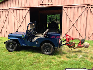
While we have 3 plows on the farm – a Ford Dearborn 2-14, a Massey-Ferguson 1-16 and a Wiard 2-12, none of these seemed to work correctly (not enough ground clearance for transportation) with the Newgren lift.  Luckily are search for plow information led us to Clint Dixon who has helped us find specifications for the operation of our lift, as well as lessons in plow geometry.
The following is an email exchange that describes what we have learned:
————————————————————————————-
Clint,
Over the weekend, I got the Newgren lift working and tried to see how it would do with my 3 plows.  All have tall masts, but wanted to see if one might work as a “show with the jeep” plow.  I hoped the Wiard would work, but no luck.  Then tried a Dearborn 2-14 and a MF 1-16.  The 1-16 came close, but was only a couple of inches off the ground.
So I’m going to build some pin-on adapters for the Newgren arms that will allow me to lift the plows high enough for transport, even if not for actual field work.  I’ll continue my search for an early Newgren plow. 
It is not the mast height, but the ground to pin height on the plow that is the problem.  Don’t know if there are any other any commercial plows that would fit the Newgren lift, unmodified.
Barry
Barry,
Well, this one took some thought and some research.
The ASAE standards for a “Category I” 3-point hitch indicate that the Lower Hitch Points on the Lower Links must lower to a height of no greater than 10-inches above the ground. They must raise to a height of no less than 32-inches above the ground. This 22-inch span is called the “power range”. (The Lower Hitch Points are the holes/balls at the ends of the lower links where the lower hitch studs on the implement directly attach.)
From Willys literature from 1951, I see that the Monroe Lift mounted on a Jeep Universal equipped with 7:00×15 tires, heavy springs, and a 180 lb. operator allows the Lower Hitch Points to lower to a height of 7-inches above the ground – well below the ASAE standard. It also allows the Lower Hitch Points to raise to a height of 32-7/8 inches above the ground – just meeting the ASAE requirement.
The Monroe Lift mounted on my Dodge Power Wagon allows the Lower Hitch Points to lower to 7-1/2 inches from the ground and raise to 32-1/2 inches. Again, meeting the ASAE standards.
I have never had the chance to compare these dimensions to a Newgren Lift mounted on a Jeep. I have to imagine the dimensions would be close if J.B. Love was trying to meet the Category I standards. If they deviate to any great degree, this could definitely contribute to what you have experienced.
I measured the distances from the ground to the center of the rockshaft on my Newgren plows, each having the tall masts. The dimension varies slightly depending upon the type of plowshares and how much they are worn, but 21-1/2 inches is an average. I do not have a Wiard, Dearborn, or Massey Ferguson near to measure, but I suspect the dimensions would not vary by more than an inch. I do not know how this dimension compares to an early short-masted Newgren.
This 21-1/2 inch measurement as taken with the plow sitting on the ground allows the plow to lower up to 14-inches into the ground. As a general rule, a 16-inch plow will work best when plowing an 8-inch deep furrow, a 14-inch plow at 7-inchs, and a 12-inch plow at a 6-inch furrow. This gives us a reserve of 6 to 8 inches of available additional plow working depth in the ground. This can be valuable when the front wheels of the vehicle pass through a washout or low spot. They can drop quite a bit before the plow is actually pulled from the ground.
This 21-1/2 inch rockshaft-to-ground measurement also means that the plow should lift high enough that the plowshare points will be about 10 to 11-inches above the ground during transport (not taking into account suspension squat from the extra weight). This is about where the plows lift to on my Power Wagon.
An early Newgren plow, with the short mast height, will no longer be parallel to the ground when raised to transport position with a Newgren Lift. The tail should be slightly high, but this has no real effect on overall ground clearance. A later Newgren plow, with the tall mast height, will be at approximately the same angle to the ground when raised to transport position with a Monroe Lift. The same thing happens with Dearborn and Ferguson plows on Ford and Ferguson tractors, and Dearborn and Ferguson plows on vehicles with Monroe Lifts.
 …
Could anything be bent on your lift? Or, do you not have original lower links and yours may be too short? I do not have the dimensions, but I could maybe get them for you. Are you sure you are getting full stroke out of the cylinder? Is the pump maybe loosing pressure before the cylinder is completely extended?
I am not aware of any plows other than what you have that would work better.
I am interested to hear what you find out.
Best Regards,
Clint
Clint,
Thank you for this great information.  The lower arms and the adjustment links are reproductions on the lift.  It is possible that they are not the proper length.   I’ll try to take some measurements of the lift range and see where I’m at now.
I had to have the cylinder complete rebuild, with a new body.  The shop reused the end caps and the end section of the rod, but I can’t be sure it was done to original specs.
I’m not sure how to thank you for taking the time to research this.  You have saved me hours of chasing the wrong issue.  I’ll keep you informed of my progress.
Barry
Hi Barry,
Well it took a while but I got some dimensions for you.
The original arms on a Newgren lift measure 21-1/2 inches, centerline to centerline, from the hole where the lift arm mounts to the rockshaft to the hole where the implement attaches.
The lift arms measure 1 inch thick and 2-1/2 inches wide.
With the arms fully lifted, the measurement from the hole where the implement attaches to the ground is approximately 27 inches (depending upon tire condition, rear suspension condition, etc. of course).
The amount of shaft that sticks out beyond the pivot block under the rockshaft is 3-1/2 inches. With the lift fully lowered, you can manually raise the lift arms, but the 3-1/2 inches of shaft will never pull out of the pivot block.
I do not know for sure, but I suspect, if you had an early short mast Newgren plow and a later tall mast Newgren plow sitting next to each other, the implement attaching points on the early plow would be a little closer to the ground than the implement attaching points on the later Newgren.
Hope this helps.
Clint
Clint,
The measurements match to what we have, for both the arm length/size and for the lift range (we did get 28″ by screwing the adjusters all the way up).  So we are on the lookout for a plow.  
Thanks again for all the help.
Barry
The good news is that we know we have the correct setup.  Need to continue looking for an original Newgren plow.  However, we may need to change our description of the Newgren lift as be compatible with standard 3PT implements.


Wow! 10 months has seen a lot happening in the Farm Jeep garage!

Sometimes, months slip by without an update, because there isn’t much going on.  But the last months have been filled with lots of activity in the Farm Jeep garage.  We’ve spent time researching and bringing our Newgren lift up to specifications.  In doing so, we discovered we really do need a Newgren plow to make it work correctly.  Added to that battle has been the continuation of leaking pumps.  The rebuild vs. buying new discussion continues.

Over the summer, Ole Blue developed some engine issues.  As long as most of our driving was on/off the trailer while going to antique tractor shows, it hasn’t been an issue.  But we want to do more and the time was right to get Blue running around the country roads.  Readers also might remember that we had purchased an engine on a stand, to use as a replacement engine.  Coupled with the clutch noise, we decided the time had come to do an engine swap.  Along the way, Barry developed a nifty tool for removing a flywheel and we also discovered that there isn’t much information out there on engine installs.

One of the reasons for developing Farm Jeep was to have a place to collect information and as a resource for us as we discover the joys and frustrations of collecting old jeeps.  Over the next few weeks, we will be updating the Web pages with our latest achievements and lessons learned.

Stay tuned!

Every decade or so..

Somehow summer slipped into fall and suddenly it was Thanksgiving again.  Time to gather firewood.  Ole Yeller has been the tool of choice for gathering and processing firewood.  The farm jeep hauls chainsaws and fuel and tows trailers full of wood to the splitter.  Even though we have farm tractors that can be used, the jeep is the better tool for the job.

Ole Yeller doesn’t get much attention.  It sets in the barn, waiting for the next job.  It has been a constant helper, starting and running without missing a beat.  But late this summer the jeep didn’t want to start.  Once it did start, it ran fine and we continued to just go about business as usual.

When Evan came down for a “jeep day”, Barry thought a quick check of Ole Yeller was in order.  The jeep started perfectly and so it was just assumed Ole Yeller had a case of bad gas.  But a couple of days later, the jeep wouldn’t start at all.

Jeeps, like old cars and tractors are pretty simple machines.  If you have fuel, spark and compression (timing) they will run.  So Barry started to check those things.  First, he pulled a plug wire and used a screwdriver to ground it to the block.  Cranking the engine produced a spark.  It was possible that the spark wasn’t strong enough to jump the plug gap.  Barry pulled the distributor cap and the cap and rotor contacts appeared tarnished.  Not a good sign.  He pulled the plugs, three of which were slightly rusted in place.  Not a good sign.  The plugs were worn with a much larger gap than normal and needed to be replaced.

Maybe it was a time for a tune-up.  Barry couldn’t remember when Ole Yeller had been tuned.  A note to Evan and a check of the Farm Jeep chronicles showed the plugs had been changed in ’03.  Almost a decade!  Definitely time for a tune up.

After a trip to the local NAPA parts store, Barry pulled the wires and reinserted them in the new cap. He also install the new rotor and plugs.  Trying to start produced nothing?  Maybe he replaced the plug wires incorrectly.  A quick check of the manual and Blue showed the plugs were wrong!

With only four wires the switch is pretty easy.  Try again.  Nothing.  OK, time to check the fuel.  It is dark in the barn (even with the lights on) and but it didn’t appear much, if any fuel was getting past the carburetor.  The after-market fuel filter is clear and appeared to have a number of rust particles inside the case.  A quick trip to town produced a replacement filter.

Clearly, fuel flow was an issue.  After the filter change, cranking the engine produced a visible flow of fuel.  But the engine still didn’t start.  OK, time to check the timing.  At least with a quick check and adjustment of the points that seems fine.  But no engine fire.  Time to head to the Internet.

A note posted on the CJ2a forum said to recheck all my work, including making sure the plug wires were correct.  There was also a link to a very good paper on timing the engine and in there was a note on how if the distributor had been changed or the oil pump replaced, it might not have been installed in the original position.  This would not change the way the engine operated but it WOULD change the location of the plug wires on the distributor cap.

It was at this point that Barry remembered an email from Evan early in the process which said “Are you sure you didn’t have the plug wires in the correct order before you fixed them? I seem to remember battling this before (although it could have been on the ’49) and that there was something odd with the firing order.”

Barry moved the wires one position clockwise AND the engine fired immediately!  What a marvelous machine.

NOTE TO THE GRANDKIDS:  When you do a tuneup in 2022/23 be sure to watch for those pesky non-standard plug wires…

The Art of the Farm Jeep

Farm Jeep as art?  We have always considered the iconic Willys jeep a beautiful piece of metal sculpture.  A grill and tailgate are part of our garage art collection.  But early last summer, Richard Saxton from the Colorado based arts group M12 (m12studio.org) contacted us at about a real farm jeep arts project.  M12 was planning an exhibition with the University of Toledo’s Center for the Visual Arts gallery and had been researching jeeps and their agriculture connections.  We were able to provide some names and contact information for some Farm Jeep historians and collectors who contributed materials to the exhibition.  A description of the short-term exhibit is here – UT News

We drove to Toledo to see the exhibit and had an opportunity to meet Ben Pond, the director of the gallery, and to talk to the students involved in the exhibit.  Some great pictures of the exhibit are here – www.facebook.com/CVAGallery . 

John Ittel’s beautiful 1954 CJ3B with a Newgren 3-point hitch is a perfect example of a farm jeep. What made a lovely-to-look-at and interesting exhibit even more special was the opportunity for the students (and the public through pictures) to see the farm jeep in action. Through a tree planting exercise, one can see both the connection to agriculture and the “universal” nature of the jeep. 

The pictures (here) show the “universal jeep” as a pickup, hauling the small trees to be planted, a passenger vehicle, hauling students, and as a tractor.  As a tractor it carries the implement (in this case an auger powered by the PTO (power take off)) to the field and engages the implement with the ground to create the holes for planting.

The planting exercise also gave us a chance to discuss some of the reasons why don’t see modern versions of the farm jeep.  Evan is showing why the jeep wasn’t favored by farmers as a tractor.  His location at the back of the jeep approximates where a farmer would be located while driving a conventional tractor, providing easy visual access to the implement.  From the jeep’s driver’s seat, it is much harder to see where the implement is making contact with ground.

We  enjoyed our visit  and discussion with the students and seeing the work of M12 and the CVA Gallery.   It did validate what we have believed all along.  A farm jeep is really a work of art.

Summertime fun – more tractor shows & fun with hydraulics

The first tractor show in May was so much fun, we were determined to attend a couple of more this summer.  It was also a good reason to acquire a jeep hauler (18′ tandem axle car hauler) for those out of town trips. 

At all three shows, we were the only “farm jeep” on display, so got lots of attention and visitors.  Having learned from the first show, we continued to use a combination of ads, signs and our notebook to explain the various bits of “farm jeep” equipment.

More fun with hydraulics

It was clear from reactions at the shows we need to display the jeep with a plow on the back to really give people a clear idea of a jeep as a tractor.  That means we need to get the lift working, again. 

Over the years we have used different pumps to power the lift, but wanted to use an authentic pump and eventually found a Newgren pump and bracket.  The pump was sent to a repair shop for reconditioning and was determined to be “worn out” and not repairable.  This sent us on another search for a replacement pump.

One of the joys of working on old jeeps is that you get to meet interesting and extremely knowledgeable people.  Our friend Lonnie knows his Newgren history and told us that the pump was the same as that used on the International Harvester model “C” tractor.  After some time search for a pump, we found one on e-bay.

The pump has been sitting in a box for a while and we did mount it, but did not connect it to the crankshaft before the first show.  So with no other shows planned, Barry decided to hook the pump up and give it a try.  The pump is connected to the crankshaft by a solid rubber disc, which allows for some movement and alignment.

The first test was a failure.  Barry suspected that the pump might be running backwards (it seemed to be pressurizing the tank).  He reversed the pump manifold, but the ram did not move.  At this point, Barry consulted with his friends over at the Tractor by Net (TBN) hydraulic forum about possible solutions.

At the suggestion of the TBN folks, we disconnected the hoses and placed them in a 5 gallon bucket half full of hydraulic fluid.  The bubbles coming from the pressure side showed that the pump was working (and rotating correctly), but not primed.  By pouring some fluid into the “suction hose” we were able to prime the pump and could see it working!

Uplifting

The Newgren lift hydraulic system is pretty basic.  The pump supplies pressure to a control valve located on the top of the reservoir.  When the control valve is in the “hold” (neutral) position, fluid enters the control valve and “dumps” directly into the reservoir.  When the lever is moved to raise the implement, the pump pressure is directed by the valve to the top of the ram, pushing the ram rod out and raising the implement arms up. When the control valve is in the “lower” position, fluid in the ram is returned to the reservoir and the ram rod is pushed in by the weight of the implement.

Since we know the pump is working, we could reconnect the hoses (pressure side to the control valve and return side to the bottom of the reservoir).  After adding fluid to the reservoir and working the control valve a few times, the arms moved up.  Success!  Sort of.

Any pressure on the arms would stop the upward movement.  No way this is going to lift a 200 pound plow.  We may still have a problem if the pump isn’t providing high enough pressure.  Or the control valve, although we have taken it apart and cleaned it, may not be working correctly.  And we have leaks in the system.  Unfortunately, those leaks appear to be coming from the top of the reservoir, which means lowering (un-installing) the entire lift.

We have had the lift in and out of two jeeps on several occasions.  While not a terribly difficult task, it is a hard balancing act, not unlike removing a transmission.  So before we attack the leak, we are going to try and build something along the lines of a transmission jack to help us get the job done.

Stay tuned.

Farm Jeep Goes To An Antique Machinery Show

There is Blue, in the middle of a row of fine antique tractors!  After years of saying we were going to take the jeep to a tractor show, we finally did it.

Following up on our last post, Thursday was final preparation day.  The hydraulic pump was bolted on the mount in front of the crankshaft pulley, but not connected and the 265 lb front bumper weight installed (with the help of the engine hoist).  Finally, we gave Blue a quick bath to get the dust off.

One goal of Farm Jeep has been to collect and share information and stories about jeeps being used on the farm.  At most shows, tractors are lined up and each exhibitor determines what, if any, information to provide.  Most provide signs with the owner’s information and the date the tractor was built but very few provide additional details.  Believing few people would have seen a farm jeep, Barry resorted to pre-retirement skills and created a short paper-based PowerPoint presentation to accompany Blue.

It had been the plan to drive Blue to the Brown County show, since we can get there on back roads, with only a short stretch of busy highway.  But between the valve and clutch noises, we felt it best to give Blue a ride on a trailer.  So early Friday Barry picked up the rental trailer and loaded up Blue for the 30 minute trip.  It was an easy drive and Barry was soon standing in front of the registration desk asking where he could park Blue.  He explained it was equipped as a tractor and didn’t want to exhibit it in the old trucks and cars section.  After a couple of phone calls, he was told to park at the end of a line of John Deere tractors.

Along with the PowerPoint slides, Barry had 3 old ads mounted in picture frames to help tell the story.  After watching people’s interest, he determined that a better plan was a loose-leaf notebook with copies of ads from the Web site would be a better idea.  The combination worked very well for the second and third days.  We were the best documented tractor and it was really appreciated by the many visitors stopping by.

People seeing the jeep fell into 3 main groups; those who had never heard of a jeep “tractor”, those who had heard, but never seen and then a very few who had used a jeep on the farm or had neighbors or friends who had farm jeeps.  This latter group provide to be the most fun, and it was clear Blue brought back some great memories.

There was a large group of “I’m sorry I sold my jeep and I sure wish I still had it” visitors who also told stories.  There were several vets who wanted to talk about their military jeep adventures and a WWII vet recalling his days in the muddy fields of Europe.  It is  unfortunate that we didn’t have a way to record some of the stories.

Friday and Saturday were extremely busy, but by Sunday noon, most of the tractors had been loaded up for home.  We stayed until after lunch, then loaded up for a quick trip home.  It was great fun and we anticipate doing more shows in the area.  Next year will will drive Blue to this one.

All Dressed Up and Someplace To Go!

The Brown County Antique Machinery show is held the first weekend in May each year.  We have been trying to make that show for the past several years, but have never been quite prepared.  We aren’t finished, but we are going to take Blue on a road trip “as is”. 

Blue is running and even though we are planning to change the motor, it is road worthy.  It lacks a working hydraulic pump and the cable to control the governor.  At least people can see a real Farm Jeep.

The first task was to install the PTO shaft.  This is normally a very simple job, involving installing and bolting the rear shaft flange on the gear box and bolting the shaft in place.  A some point, the splined shaft on the rear of the gear box had been damaged.  The gear box had to be removed and the bolt hole had to be re-tapped.  So the normal 30 minute job turned into a 3 hour task.

The gearbox turned easily, so we filled it with gear oil and started the jeep.  The PTO worked perfectly.  Except for a small leak on the back of the box.  We will need to remove the box and see if it is a quick fix or a tear down.

Several years ago, we find a Willys belt pulley assembly on e-Bay.  It was mis-identified as being for a tractor, but we had done enough research to know a Jeep pulley when we saw one.  It was a paper pulley, instead of the more common steel type, and it had to be rebuilt.  There is still a company – www.paperpulleys.com – that rebuilds paper pulley drums and we had them build a pulley using our frame.  The drum has been sitting on a shelf for a few years.

The pulley gear box had been on the shelf too and we decided to just clean it off and install it as a show item.  The assembly was a simple bolt-on process and the drum turns freely.  We need to paint the gearbox, but that can wait.

In the picture above, you can see the lift arm to the right of the drum being held in place by an original adjustable link.  The second link is rusted solid and will need some work.  For this show, we have used the reproduction links we had on hand.  This should at least give folks a idea of how the lift operates.

Other than a quick bath, we are ready to go.  We will report on our first outing

Farm Jeep Spring

Farm Jeep is coming out of its winter hibernation.  With the garage doors opened we changed the coil on the stand engine, to prepare it for the 12 volt 3a.  After a test start, we removed the engine from the stand and will prepare it for the exchange.  That means removing the face plate, which is a 2a style, and replacing it with 3a face plate.

Too much of a bling thing..

Getting the 3a to be street legal was a year-long struggle.  Among the requirements was working wipers.  The easiest fix was to install two “universal”12 volt wiper motors.  This project was chronicled in an earlier post.  Somehow, those chromed motors stuck out like a sore thumb on the windshield.  There had to be something better.

Original windshield equipment included a vacuum wiper motor on the driver’s side and a manual “hand” wiper on the passenger side.  Using a vacuum motor would mean changing the fuel pump (to power the motor) and might be a future change.  For now, we are going to use a painted motor with a built-in switch.

An original hand wiper appeared on e-bay and we purchased it with the idea of restoring it.  However, it was too far gone and a reproduction was our only option.  The reproduction is for the 2a, with the shorter, split windshield.  It is 2″ too short to work on the 3a.  A 2″ section of rod was welded in the middle to make it the proper length.  We need to find a grommet to finish mounting the wiper.

Ahead is an engine exchange and maybe a wiring re-route to accommodate the governor cable.